The following procedures generally follow those as specified by ASTM F2620: Standard Practice for Heat Fusion Joining of Polyethylene Pipe and Fittings. ASTM F2620 notes that fusion procedures are available from various fitting and pipe manufacturers and are acceptable if proven to produce reliable joints. Some jobs may require specific certification for fusion operators.
Tools Required
The following is a list of tools you will need to produce quality HDPE socket fusion joints. A variety of complete kits that contain all the required tools for specific pipe sizes are available.
Socket Fusion Heater Tool / Iron
Heater Bag
Timer
Pipe Cutter
Lint free, non-synthetic cloths
Socket Fusion Procedure Overview
1.Attach the correct socket faces, which are in good condition, to the heating body of the tool.
2.Connect tool to an adequate power supply (120 volts A.C.)
3.Heat faces between 490 and 510° F. Adjust temperature as necessary.
4.Square pipe ends with a pipe cutter designed for plastic pipe.
5.Wipe pipe end and fitting clean.
6.Chamfer pipe.
7.Insert pipe end into the properly-sized depth gauge and attach the proper sized cold ring onto the pipe.
8.Begin timing the “HEAT CYCLE” as soon as the pipe and fitting are properly positioned on the pre-heated socket faces.
9.At the conclusion of the “HEATING CYCLE”, snap the pipe and fitting from the tool.
10.Within three seconds, push the pipe and fitting together squarely without twisting.
11.Hold firmly together for the specified “HOLDING TIME”.
12.Clean hot socket faces clean with a clean, dry, non-abrasive cotton cloth.
13.Visually inspect each fusion joint.
Socket Fusion Procedure Details
Some of the information in the procedure below is specific to Geo-Flo’s Socket Fusion Heating Tool. Refer to the heating tool manufacturer for specifics on power ratings and temperature adjustment.
- 1.PREPARE THE TOOL
- Attach the correctly sized socket fusion faces for the pipe size being fused to the heating tool.
- The faces shall be tight against the tool to ensure a good heat transfer.
- Socket faces should be in good condition with little or no loss of non-stick coating. Faces which are in question shall be replaced before proceeding.
- Loose socket faces impair heat transfer.
- Attach the heating tool to an adequate power supply and allow sufficient time for the tool and fusion faces to come up to a surface temperature of 490° F to 510° F.
- Temperature reading on fusion tool will be higher than the temperature on the faces
- Place the tool inside an appropriate heater bag or other enclosure to reduce heating time, especially in cold or windy weather
- Single face heating tools draw 400 watts, while double face tools draw 500 watts. Allow a minimum of 5-amp service.
- Inadequate power supply and inadequate power cord causes loss of amperage resulting in heat loss.
- Other tools on the same power source may cause loss of amperage and heat.
- 2. CLEAN THE SOCKET FACES
- All heater faces have a thin layer of non-stick coating that is easily scratched or scraped off. This coating prevents melted PE from adhering firmly to the heater faces and must be kept clean of plastic residue.
- Metal tools should NEVER be used to clean the heater faces. They will scratch and remove the coating.
- Clean, dry, lint-free, non-abrasive cotton rags are recommended for cleaning.
- All-cotton rags are recommended because rags containing a substantial amount of synthetic fibers may melt and char against the heater surface.
- If the non-stick coating becomes worn or scratched, the heating faces must be replaced or recoated.
- Melted PE adheres firmly to the heating iron and is more difficult to remove at places where the coating has been scraped off the faces.
- In addition, since the coating acts as an insulator, heat transfer in the uncoated areas is greater and local overheating can occur.
- NEVER lay a fusion tool on the soil or grass when the heat cycle is completed. Return it to the heater bag, if possible, or at least lay it on the heater bag. Soil will contaminate the joint and is abrasive to the coating; grass may burn and char on the heater surface.
- 3. CHECK FACE TEMPERATURE
- Heating tool thermometer indicates internal tool heat temperatures, NOT the socket face surface temperatures.
- Socket face temperatures MUST be 490 to 510°F. This is especially critical in cold weather.
- Check the heater temperature with surface pyrometer or Tempstick® crayon indicators often to make sure the thermometer or other temperature measuring device is reading accurately.
- Don’t use temperature indicating crayons on the surface of the non-stick faces where the pipe and fitting come in contact.
- Under heavy use conditions, or during cold or windy conditions, check the temperature more frequently.
- To increase temperature, turn set screw counter-clockwise. A quarter of a turn equals a 30-degree change. Do not turn excessively.
- 4. PREPARE PIPE END AND FITTINGS
- Cut the pipe end squarely
- Be sure to cut off damaged or oval ends of the pipe.
- Do not use flattened, damaged or out-of-round pipe.
- Inspect every fitting for out-of-roundness or damage
- Pipe and fittings shall not be used if an interference fit is not evident.
- Allowable tolerances ensure interference fit
- When heat fusion is applied, the pipe and fitting will readily assemble.
- Check inside pipe for contaminants or obstructions
- Clean the pipe and fitting inside and out with a clean, dry, lint-free, non-synthetic cloth such as cotton
- If the pipe/fittings cannot be cleaned with a dry cloth, wash with water
- Fitting and pipe surfaces shall be clean and dry before starting fusion
- If the pipe/fitting appear to be contaminated with soap, oil or other substance, you may use a 90% isopropyl alcohol solution or acetone
- Do not touch surfaces to be fused with your hands after cleaning; oil from your hands will contaminate the joint
- If the pipe/fittings cannot be cleaned with a dry cloth, wash with water
- Chamfer the outside of the pipe.
- Remove shavings and chips inside the pipe end. These will contaminate the joint.
- 5. USE THE PROPER DEPTH GAUGE AND COLD RING
- Place the chamfer/depth gauge flush on the end of the pipe
- Clamp the correctly sized cold ring around the pipe, adjacent to the depth gauge.
- The cold ring clamp/plier may need to be adjusted for a snug fit, particularly in very cold weather as the pipe contacts when cold
- After securing the cold ring clamp, remove the depth gauge.
- PIPE END AND FITTINGS ARE NOW READY FOR HEATING.
- 6. HEATING THE PIPE AND FITTING
- Ensure the heating faces are clean. Clean with a cotton cloth.
- Check the faces of the heating tool for proper temperature (490-510°F)
- Grip the pipe behind the cold ring
- Do not use the cold ring as a handle; slight slippage could occur affecting the depth of pipe penetration into the fitting
- First, firmly seat the socket fitting on the male face of the heating tool.
- Then place pipe into the female face and press until the cold ring meets the face.
- HEATING TIME STARTS NOW.
- While holding the fitting and pipe firmly in a fixed position, heat both for the heating cycle shown in Table 1.
- Only apply enough force to prevent the fitting/pipe from backing out
- Too much pressure against the socket face plate will cause a rollback of the fitting edge, shortening the actual socket depth and creating a gap when the pipe and fitting are joined
TABLE 1: HDPE 3408/3608/4710 CYCLE TIMES*
| Pipe Size, IPS | Heating Time (seconds)1 | Cooling Time (seconds)2 | Handling time (minutes)3 |
| 3/4” | 8-14 | 30 | 5 |
| 1” | 15-17 | 30 | 5 |
| 1-1/4” | 18-21 | 60 | 5 |
| 1-1/2” | 20-23 | 60 | 5 |
| 2” | 24-28 | 60 | 5 |
- Heating Time is measured from the time the cold ring contacts the heating face (i.e. when the pipe is fully inserted. Always use a timer for accurate cycle times. ↩︎
- Cooling Time is measured starting from the time the joint is made. The joint must be held for this time before the cold ring clamp is removed. Always use a timer for accurate cycle times. ↩︎
- Handling time is the minimum additional amount of cooling time after the cold ring has been removed that must elapse before subjecting the joint to any stress such as burial, testing, and/or fusing the other end of the fitting. This time should be extended when working against the coil “memory” of the pipe or whenever the pipe orientation may cause stress at the joint. ↩︎
*Extremes in weather will require special precautions. Cycle times may need to be extended in very cold weather
- 7. COMPLETE THE JOINT
- When the heating cycle is complete, remove the pipe and fitting from the fusion faces with a quick snap action. DO NOT TWIST.
- Quickly inspect the heated parts to ensure all interfacing surfaces have been melted and are free from contamination.
- If the melt is not complete or you notice contamination, stop. Do not attempt to assemble pipe and fitting. Cut off the melted pipe end, use a new fitting, and repeat fusion steps above
- Within 3 seconds after removing the pipe and fitting from the fusion faces, firmly push the melted fitting squarely onto the pipe until it makes firm contact with the cold ring. DO NOT TWIST.
- Hold the fitting firmly in place for the total cooling time shown in Table 1 to ensure proper alignment.
- IMPORTANT: If you are uncomfortable with any aspect of the fusion process for this joint (cycle times, melt, fusion pressure, twisting, contamination, etc.) cut it out and start again. Every fusion joint is critical. One bad joint may cost thousands of dollars to repair later.
- 8. CLEAN FUSION FACES
- Clean faces immediately after every fusion. All visible material must be removed.
- Material left on the socket faces will carbonize and disrupt good heat transfer. It will also form a barrier over the non-stick coating, causing poor release. Without a smooth release, dirty socket faces will strip off the molten surface plastic, resulting in a poor joint, possibly complete joint failure.
- Use a clean, dry, non-abrasive cotton cloth to clean the socket faces.
- Do not use synthetic cloth, wet cloth or hard or metal objects which could damage the non-stick surface of the socket face.
- Wet or damp rags could significantly lower the temperature of the faces.
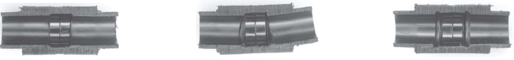
- 9. INSPECT THE JOINT
- The melt surface on the face of the fitting should have a uniform impression of the cold ring completely around the circumference.
- Non-uniform impression is a sign the fitting/pipe were misaligned during fusion
- Missing impression indicates that the joint is too short (i.e. pipe not inserted to full depth)
- There should be no gaps or voids.
- Gaps or voids may indicate that the fitting was not removed straight from the heater face, pipe/fitting were not pushed straight in, or twisting occurred during the fusion process
- The center axis of the fitting should be parallel to the pipe, not angled.
- If possible, look in the end of the pipe/fitting to ensure that there is no reduction in diameter
- Collapsed pipe may indicate too high of tool temperature, excessive heating time, or improper cold ring placement.
GOOD BAD-Misaligned BAD-Short insertion
- 10. TESTING
- Upon completion of the installation, the system should be hydrostatically tested. Testing must be completed prior to burying joints.
- Hydrostatic testing of the system is to be conducted according to local code requirements, if they exist.
- Record the results of the testing
- It is good practice to record results of your fusion on each customer’s job .
- Shoot photos/videos of the fusion joints, pyrometer, and test gauges.
- Save the results to a folder with the job name; provide a copy to the customer.
Special Provisions
- Fusion should not be conducted under temperatures under -4 F (-20 C).
- When ambient is at or below this level, you must use a heated shelter or other means to conducted the work
- Keep the heating tool in an insulated bag and out of the wind, rain, snow, etc.
- Use a barrier to protect the fusion area from wind
- PE pipe is tough but is subject to damage at sub-freezing temperatures so take precautions when handling the pipe
- PE pipe and fittings will contract during cold temperatures
- Leave fittings in a conditioned space or your truck until they are needed
- If the cold ring slips on the pipe, you can use a second set with a shim directly behind the first. The first cold ring allows the pipe to expand as normal when heating
- In very cold temperatures, the pipe may barely contact the female heating face. You may need to increase the heating time to allow the pipe to expand to normal size, then melt as normal. It is recommended to run a few tests to check for a complete melt around the pipe. Add three seconds to each subsequent test until you achieve a uniform melt all around the pipe. Do not heat for longer than necessary.
- Check face temperatures regularly. Do not increase the fusion temperature above specification.
- PE pipe will soften during high ambient temperatures (and left in the sun) increases the likelihood of kinking the pipe. Hard kinks in the pipe should be removed and repaired.
- Heat loss from tool will decrease under high ambient temperature conditions. Always check the heater faces to be sure the temperature is within specification.